Engines - Controls (PW4060)
Forward Thrust LeversForward Thrust Levers are provided to control engine forward thrust requirements from idle to maximum power. Reverse Thrust Levers
Thrust Management Computer
|
|
The Thrust Management Computer calculates a reference EPR based on existing pressure altitude and ambient temperature data from the air data system for the following modes:
- TO - takeoff
- D-TO - Assumed Temperature Takeoff
- CLB - Climb
- CLB 1 - Climb One
- CLB 2 - Climb Two
- CRZ - Cruise.
- CON - Continuous.
- GA - Go-Around
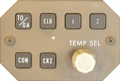
Thrust Mode Select Panel
These modes can be selected with the Thrust Mode Select Panel (TMSP). The inner Thrust Reference Set control on the EICAS control panel must be pushed in for the Thrust Reference modes to be displayed on EICAS. The selected Thrust Reference mode is displayed above the EPR indicators. The digital Reference EPR is displayed adjacent to the mode display. When the EPR bug is green, it is positioned on the EPR scale at the same value as the digital reference EPR.
The Thrust Mode Select Switches provide the capability of selecting different thrust modes for each phase of flight:
- The TO/GA switch is used to select takeoff thrust on the ground and go-around thrust in-flight.
- The 1 and 2 switches are used to select a Reduced Climb Thrust. When reduced takeoff thrust rating one or two is selected, this automatically pre-selects the associated reduced climb one or two.
- The CLB switch is used to select climb thrust in-flight. If reduced climb thrust one or two was pre-selected, pushing the climb switch in-flight selects CLB 1 or CLB 2.
- The CON switch is used to select Maximum Continuous thrust in-flight.
- The CRZ switch is used to select Cruise thrust in-flight.
- The Assumed Temperature Selector on the TMSP or the CDU TAKEOFF REF page is used to set assumed temperatures when reduced takeoff thrust is desired. The assumed temperature is displayed above the Thrust Reference Mode.
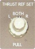
To manually set reference EPR values the Thrust Reference Set Control is pulled out, MAN appears as the thrust mode annunciation and the EPR bug slews to 1.55.
Manual reference EPR values can then be set by rotating the inner control. The outer control of the Thrust Reference Set Control is used to select the desired EPR indicator(s) for manual EPR display. The autothrottles do not respond to manually set Reference EPR values. When the inner control is pulled out, the autothrottles remain in the active TMC mode. The TMSP remains operable and the autothrottles respond to TMSP mode changes, but selected Thrust Reference Mode displays are inhibited.
When the AFDS VNAV mode is engaged, the EPR bug may be magenta. When the EPR bug is magenta, it is positioned at a nominal target EPR by the FMC, which may not correlate with the digital reference EPR. In VNAV, the FMC controls Thrust Mode selection automatically to meet thrust requirements for the active vertical mode of operation. The FMC does not have the capability to select reduced climb thrust values; these values must be selected manually with the 1 or 2 Thrust Reference Mode Select switches.
The Thrust Reference mode, Reference EPR and Target EPR Bug indication are not displayed when the reversers are fully deployed.
Assumed Temperature Takeoff
The Thrust Management Computer calculates the reference EPR for assumed temperature reduced thrust takeoff. The assumed temperature can be entered manually on the CDU TAKEOFF REF page (PEGASUS) or selected with the assumed temperature selector on the TMSP. The assumed temperature is displayed above the thrust reference mode.
When the Assumed Temperature Selector on the TMSP is initially rotated clockwise, a reference temperature is displayed on EICAS. This temperature also appears on the FMC CDU TAKEOFF REF page as THRUST (PEGASUS). Further clockwise rotation of the selector increases the assumed temperature by 1 degree centigrade per click. The reduced thrust annunciation of D-TO appears when the assumed temperature selected is above ambient. If the ambient temperature is greater than the initially displayed reference temperature, D-TO and reduced thrust occur when the assumed temperature selected exceeds ambient.
Counter clockwise rotation of the selector reduces the assumed temperature by one degree centigrade per click.
Assumed temperature takeoff thrust is limited to a 40% reduction of maximum takeoff thrust or selected climb thrust, whichever is the greater thrust value.
When the limit is reached, further clockwise rotation of the selector or changing the value entered in the CDU TAKEOFF REF page (PEGASUS) does not change the displayed assumed temperature or reference thrust value.
Reduced Climb Thrust
Two levels of reduced climb thrust are available with the 1 and 2 mode switches on the Thrust Mode Select Panel. Below 10,000 ft, Climb 1 is approximately 90% of climb thrust and climb 2 is approximately 80% of climb thrust. Climb 1 or 2 can be pre-selected in conjunction with the TO, D-TO, CON and CRZ Thrust Reference modes.
Above 10,000 feet, reduced climb thrust gradually changes to reach full climb thrust by 12,000 feet. The 1 or 2 annunciation disappears from the display by 12,500 feet.
Above 10,000 feet reduced climb thrust gradually changes to reach full climb thrust by 30,000 feet. The 1 or 2 annunciation disappears from the display by 30,500 ft.
Electronic Engine Control
The thrust system consists of a dual channel, full authority Electronic Engine Control unit without any hydro-mechanical backup. Each EEC is powered, when the engines are operating, by a dedicated permanent magnet alternator (PMA) independent of airplane electrical power. The EEC commands constant engine output for a given thrust lever position. EPR is the prime thrust setting parameter, N1 is alternate.
The EEC continuously computes the maximum thrust limit which is presented as an amber radial on the EPR display. Maximum rated thrust is available in any phase of flight by moving the thrust levers to the full forward positions.
Primary (EPR) Control Mode
Both engines normally operate in the primary mode to control thrust. In primary control mode operation, target EPR for current thrust lever position is computed as a ratio to the full throttle position. During rapid thrust lever movements, the difference between the engines actual EPR and the EEC commanded EPR is displayed as the command sector on the EICAS EPR display.
The EICAS advisory message L/R ENG CONTROL and ENGINE CONTROLS displays when faults are detected in the engine control systems. These messages are designed to prevent dispatch with these faults.
The dual channel system provides redundancy of inputs to the engine fuel control
Alternate (N1) Control Mode
If the EEC is unable to maintain EPR control, the EEC will automatically revert to the alternate control mode. The alternate control mode may be manually selected by using the flight deck EEC switches. When operating in alternate control mode, the ALTN light illuminates and the EICAS advisory message L/R ENG EEC MODE displays to indicate the EEC has reverted to the alternate mode.
In the alternate control mode, target N1 for current thrust lever position is computed as a ratio to the full throttle position. Due to changes in thrust produced at constant N1 setting during changes in ambient conditions, alternate control mode operations during climbs and descents require thrust lever adjustment to maintain constant thrust. Thrust is controlled in a manner similar to conventional fuel controls.
The alternate control mode has a dual channel system providing redundancy of inputs to the engine fuel controls. Automatic thrust limit protection is not available. In the alternate mode, the EICAS caution message L/R ENG LIM PROT displays to indicate the commanded N1 exceeds the maximum N1.
Overspeed Protection
In either control mode the EEC also provides N1 and N2 red line overspeed protection. If N1 or N2 approaches overspeed, the EEC commands reduced fuel flow. The EICAS advisory message L/R ENG RPM LIM PROT displays to indicate N1 or N2 is at the red line limit.
The EEC does not provide EGT over-temperature protection.
If engine limit protection is not available, advancing the thrust levers full forward should be considered only during emergency situations when all other available actions have been taken and terrain contact is imminent.
Idle Selection
There are two engine idle speeds:
Minimum Idle. Minimum idle is a lower thrust than approach idle and is selected for all ground operation and for all phases of flight except approach and landing.
Approach Idle. Approach Idle is selected automatically whenever this higher idle setting is required for proper system operation.
During approach and landing when the Landing Gear is down or the Flaps are set to 25 or 30, the idle speed setting increases from minimum to approach. Approach idle setting is maintained until 5 seconds after touchdown to facilitate a faster acceleration for go-around or reverse thrust operation. After the 5 second delay the approach idle speed reverts back to minimum idle to help minimize the landing roll. In-flight when engine anti-ice is turned on, the idle speed setting also automatically increases to the approach setting to maintain higher idle speeds during icing conditions.
The EEC selects these idle speeds automatically.
Rotating the engine start selectors to continuous manually selects approach idle.
The EICAS advisory message L/R ENG LOW IDLE displays to indicate that an engine failed to go to approach idle.
The EICAS advisory message IDLE DISAGREE displays to indicate that the engines are at different idle settings. Either one engine has failed to go to approach idle when required or one engine has failed to return to minimum idle. Inflight, to ensure that approach idle is available if required, the thrust lever on the engine with the lower RPM should be advanced to match the engine with the higher RPM.